FMX-4 Facetmobile - есть ли у кого чертежи

Dear all,
Actually this model is not really 100% a FMx5, but a model that after studying the principle of the facetmobile FMx4.... I made some mokeups and trials to understand the design. The story began after cardborad models, then the GTx9-01 (1m span).... crashed on second flight, then the ... GTx9-05 (1m50 span) to check the behaviour (pretty satisfying !), and right now the GTx9-07 (2m45 span), which began to be really precise. The story isn't finished ...
The idea behind those models is validate the design, which is pretty good now, of a light and safe machine scale 1 (6m span), in oreder to build it by myown and fly with...because I'd like to fly with, of course.
We work as a team with other friends, especially one very good radiocontrol pilot.
Any request or idea, please don't hesitate to ask... :)
Regards.
 
some more picture ...
 

Вложения

  • GTx9-07.JPG
    GTx9-07.JPG
    101,8 КБ · Просмотры: 120
and drawing.
Rgds.
 

Вложения

  • GTx9-07-C_-_3views.pdf
    197,6 КБ · Просмотры: 164
эх, говорила мне мама - учи английский... :-[
 
Большое спасибо за материал, есть над чем подумать. Давно следил за вашей работой через http://www.youtube.com.
Очень хотел узнать почему разбилась эта модель?
http://www.youtube.com/watch?v=Ytv1xOhOkaI
На видео плохо видно.
И почему на последней модели отказались от winglets?
С уважением.
 
With many thanks for material, there is on than think. Long ago keeped a check on your work through http://www.youtube.com.
Much wanted to hear why was split this model?
http://www.youtube.com/watch?v=Ytv1xOhOkaI
On video is bad seen.
And why on the last model abandoned to winglets?
Respectfully yours.
Upstairs    deneb

Вот перевёл ::) , прошу не обижаться - ?! ;)
 
You're welcome, no problem ! And your english is certainly better than my russian...
So answering your questions :
Why did the -06 model breakdown ? because the center of gravity was not located correctly, and because the plan wing was not stable on the longitudinal point of view. Another thing also, confirmed by the radio pilot, is that I embarqued a video transmitter which was unfortunatly disturbing the radio control. We see that the movements of the elevons are very large, but that was not due to the pilot...So now I just install a recorder on board, no more perturbating system. On top of that I reduced the size of the wing in front of the craft, and this reduces the stability.
Now regarding the winglet : Actually I have to put a certain vertical surface to secure the yaw stability. That can be in the middle (a rudder), two winglets but with small rudder, or both systems. I'd like to check the one which is less giving drag....
Don't hesitate to share informations...
Regards.
:)
 

Вложения

  • GTx9-07-C_A0_1_.pdf
    48,2 КБ · Просмотры: 156

Вложения

  • fmx-4_and.JPG
    fmx-4_and.JPG
    28,8 КБ · Просмотры: 125
Yes, of course.
Two advantages at least :
1. The diedral angle gives you more staibilty
2. It allows you to give some space to the pilots whitout making a "mountain" on the upper surface....

Actually I tried to have a airfoil profile of 12% at the root, coming from a airfoil of 18% in the middle. I also wanted to equilibrate the profiles all along the span....

No problem to answer all questions... fell free to ask, I started also by reading and asking questions....This is the only way I know to learn. Ask why, understand, try, make errors, learn from errors, make your own experience !
:)

If you want to read some interesting book, try "Nurfluegel..." from Karl Nickel.
And look on internet at Rutan aircrafts principles, Horten principles (look at PUL10), B.Wainfan, Dyke delta, etc...

You can start with cardboard cutting, a small scale, then you launch your trial mokeup manually....

Very friendly,
Rgds.
 

Вложения

  • GTx9_start_of_development.pdf
    71 КБ · Просмотры: 122
Today's weather is nice .... So I took some pictures.
 

Вложения

  • P1020754_Vue_de_face.JPG
    P1020754_Vue_de_face.JPG
    124,6 КБ · Просмотры: 108
and side view...
 

Вложения

  • P1020751_Vue_de_cote.JPG
    P1020751_Vue_de_cote.JPG
    145,8 КБ · Просмотры: 120
Well, actually I take very simply roughly 200W/kg. So the model is 10kg, so engine will require 2kW.

Then the propeller is calculated with the usual formulae :
P=k*D^4*p*N^3
where
P is the absorbed power by airscrew in W
k is 1 to 1,2, according to airscrew quality
D is airscrew diameter in ft (1m=3,281ft)
p is the step in ft
N is the rotation speed in 1000tr/min

For example in my case, for this model :
Supply voltage 24V
Kv of motor = 200 V/tr/min
So maximum rotation speed (full throttle) = 4800tr/min
At this speed, an airscrew of 25"x12" will absorb 2300W.
and the intensity pulled from battery pack will be around 95A.

The electrical motor I have is a brushless motor able to work under 48V and able to deliver 6000W. So it is oversized, clearly, because the measurement confirmed the calculations with an intensity close to 100A under 24V.

For real size aircraft, the formulae keeps the same, of course...
A propeller of 70"x40" rotating at 2500tr/min pulls 67kW (90cv).

Hope I gave you a comprehensive explanation... Don't hesoitate to ask me if I can help you...
Regards.
 
Actually I target to keep the maximum take off weight under the 450kg to keep in the ultralight legislation rules for 2 persons.
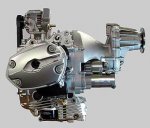
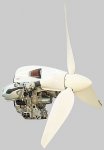
The engine will be from BMW flat twin motorcycle (90cv).
A reducer will be between the propeller and the engine.
Some thing like on the attached picture.
Rgds.
 

Вложения

  • m09.jpg
    m09.jpg
    18,1 КБ · Просмотры: 115
  • m01b.jpg
    m01b.jpg
    10,6 КБ · Просмотры: 117
Hi Deneb,
No problem.
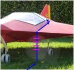
To enter in the plane, the pilot and the passenger have to go from the front of the machine to the cab, with a stair which is included in the leading edge, to the cockpit. Along the root, at Y=1000. Look at the model...You can go in from the top, as usual.
About the weight, no problem too. Because of the low strengh inside the skin, the whole machine is "empty", full of air. It means that the efforts doesn't require so much material....You don't need material where you have no strengh ! ...Short span, and large root section, then low strengh...
Then the machine itself keeps very light.
Regards.
 
Hi Deneb,
Please find attached a picture of the way to go in the cab...
Regards.
 

Вложения

  • GTx9-07_-_How_to_climb_in_the_cockpit.jpg
    GTx9-07_-_How_to_climb_in_the_cockpit.jpg
    16 КБ · Просмотры: 126
Hello Deneb,
So long time without any message...
Yes, last weekend we let the wing fly again.

You can see the video on youtube, as before.

Three main conclusions :

1. The view from cockpit is OK, for take-off and for landing. Good.
http://www.youtube.com/user/gtex09#p/u/8/G4xJmscT36k

2. At high speed, for example when diving, we observe a lack of manoeuvrability, like a loose of elevons efficiency. This has been also observed just after a diving, even in horizontal flight, buut always at high speed. We tried to understand and put some wires on the top skin of trhe wing, to see the flow. Actually, there is a flow separation at high speed explaining the lack of efficiency on control. Then conclusion is that we have to improve the shape of the "equivalent" airfoil, especially close to the tip. I will make a modification within next days and come back for trials.
Look at the 2 videos on the same time, synchronise when take off...
http://www.youtube.com/user/gtex09#p/u/1/j2xurG6Ni1U
http://www.youtube.com/user/gtex09#p/u/0/Yvyg2HaAzec

3. At low speed now : very good, very manoeuvrable and responsive. Good.
http://www.youtube.com/user/gtex09#p/u/16/1CuLzW1pMZs

Conclusions : some more modifications... and that will be OK.
Regards.
gtex09
 
Hello gtex09.
So long time without any message... yes, family problems.
home crisis... :(
 
Назад
Вверх