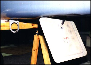
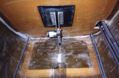
По поводу электрического привода посадочного щитка. Пока не понял как он устанавливается 🙁
AN ELECTRICALLY ACTUATED LANDING BRAKE
By MIKE MELVILL
From CP72, Page 8, (July, 1992)
This question has been asked many times. remember discussing this with Burt on a number of occasions. The answer was always, "Why mess around with a nice simple, light-weight system that has never given any problems?". I agreed with this argument at that time and never seriously considered such an idea until recently.
Occasionally I heard from builders and flyers who had installed linear actuators but I did not take these seriously until my good friend and colleague, Doug Shane, made this modification to his own Long-EZ here 'at Mojave. He used a Warner electric linear actuator and told me it was rather easy to install and that it worked very well in flight. Being a gadget freak (my wife, Sally, repeatedly tells me I am) I decided I had to have one! I researched the Warner actuator that Doug used and was at the point of ordering one when another friend, Norm Howell, (also a Long-EZ builder) showed up at Mojave with a data sheet on a different electric linear actuator made by Pittman, one that was much smaller and lighter than the Warner. Also, it reportedly could generate more "push" power than the Warner. Norm wanted to order one for himself and offered to include an order for me. I gave him a check and commenced designing the mounting bracketry and hardpoints.
A couple of weeks later, I had the new actuator in my hands and I could not believe how tiny and how light-weight it was. The electric motor was 28 volts which is compatible with N26MS, my Long-EZ. Only one thing disappointed me about it and that was it did not have integral limit switches to shut the motor off at either end of its travel. Doug's actuator did have these limit switches included in the design which would make it easy to install and wire up. Instead of integral limit switches, this Pittman actuator Y&, constructed in such a manner as to limit the total travel to 4" at which point the electric motor 'S continues to run but the actuator stops. This occurs at both ends of the travel.
While this is not an ideal system, it will drive the landing brake down and up with at least 100 lbs. of actuating force and will support at least 225 lbs. while extended and static. This actuator takes about 5 seconds to go from one end to the other of its travel (4").
I first removed the manual landing brake actuating mechanism which included the LB-13 handle, the cables, the LB-1 steel weldment, the LB-21 pushrod and the LB-9 plywood gusset This left the landing brake hinged onto the bottom of the fuselage and the LB-18 brackets remained in place on the landing brake.
The Pittman actuator comes with a 1/4" rod end installed on the end of the actuator and, happily, this rod end fits perfectly in between the two LB18 brackets mounted on the landing brake. The Pittman actuator fitted without interference through the 1"X 2" hole in the floor throughout the travel of the landing brake. This left me with only having to figure out how to mount the motor end of the actuator to the aft face of the front seat bulkhead.
I elected to cut into the aft face of the front seat bulkhead for installation of the mounting hardpoint because this moves the motor motor end of the actuator forward partially into the bulkhead allowing a little more baggage room on the floor of the rear cockpit. Working on the aft face of the front seat bulkhead is much harder to do and were I to do it again, I may simply cut into the forward face. I removed glass skin and PVC foam and sanded the inside surface of the forward glass skin before floxing in a rather large solid glass insert (1/4"x3"x5"). After cure, I bevelled the foam and glass and laid up 3 plies of BID over this insert and lapping into the bulkhead. The reason I installed such a large insert is simply crash worthiness. I would not want the actuator to penetrate the front seat bulkhead in the event of an off field landing or crash.
I fabricated two small brackets from 2023-T3 aluminum angle, bolted them to the top end mount of the actuator, held the landing brake firmly closed and drilled through these brackets and the insert in the bulkhead. After these brackets were installed, I found I had to make a small adjustment at the lower rod end to adequately snub the landing brake in the up and closed position.
I drilled a hole through the front seat bulkhead and ran two 20 gauge wires through this hole over to the left side and forward to the instrument panel. I mounted a momentary-on DPDT, center off switch on the left side of the panel just above the throttle when it is in the full throttle position. I wired the switch through a 3 amp fuse to the 28V buss. The "sense" of the switch is switch handle up, landing brake up. Switch handle down, landing brake down. With this particular installation, the landing brake is extended or retracted in 4-1/2 seconds while static on the ground.
ADVANTAGES. This is an easy retrofit or initial installation requiring only a couple of evenings of work. It is as light, or lighter, installation than the mechanical system. The main advantage in my opinion was that it allowed me to completely remove the LB-9 plywood bracket. This bracket has been the subject of two MAN/GND call-outs in the CP where the concern was that this plywood bracket may penetrate the front seat bulkhead in an off field landing or crash. I was very happy to be able to remove this LB-9 bracket.
DISADVANTAGES, Cost. This electric actuator is not cheap, none of the suitable actuators are cheap. My installation cost me $180.00 not including the cost of the original parts which I removed and discarded. Any electrically actuated mechanism may be more complicated and therefore less reliable than a mechanical mechanism. I don't worry too much about an electrical failure or motor failure because the landing brake is not critical to safe flight.
This change that I have made to my own personal Long-EZ is not a RAF or Burt Rutan approved change. As a gadget freak, I liked the idea so I designed it and made the change myself. If any builder/flyer out there is interested in making a similar modification, send a SASE to me at RAF and I will provide the name and address of the actuator manufacturer. Keep in mind that some manufacturers are very gun-shy of selling you anything that might be used on an airplane so some discretion is required when you purchase one of these.
FLIGHT TEST RESULTS, Testing has shown that the brake can be extended or retracted at any speed below 110 KIAS. Retraction or extension time is approximately 5 seconds. One shortcoming that showed up in flight test was that an appropriate amber warning light is required to warn the pilot anytime the landing brake is not closed. This is a mandatory requirement. I have not flown it often enough at this point to decide if I really prefer it over the manual mechanical system, however, knowing that the LB-9 plywood bracket is no longer installed makes it worth it.

